Basic Usage of WireGuard on Windows
WireGuard is known for its simplicity, efficiency, and security, and the official Windows client continues this tradition. Unlike the command-line operations on Linux, the Windows version focuses more on graphical management and tunnel switching. The configuration logic mainly revolves around generating key pairs and editing .conf files.
The following configuration is based on two Windows devices. Node A has a public IP address (or has port mapping configured) and acts as the "central node" waiting for connections. Node B is behind a NAT (internal network) and actively connects to Node A to achieve mutual communication.
The core logic is: A is responsible for "waiting for connections," while B is responsible for "finding A." This "waiting" does not mean a persistent connection is established; instead, B maintains the data channel between the two by actively sending packets and establishing a keepalive mechanism. When B actively sends packets to A, B also leaves its external port on the router's public side, allowing A to send response data back to B.
1. Preliminary Preparation: Installation and Key Generation
-
1-1. Two Windows devices: Node A (with a public IP), Node B (behind NAT, just needs internet access).
-
1-2. Install the WireGuard client: The official website is currently blocked in China. You can find it on some domestic software sites, but be careful to ensure it is used only within China (e.g., from home to office). Cross-border forwarding will also be blocked.
-
1-3. Confirm A's port is reachable: A needs to allow a UDP port (e.g., 6000). Add an inbound rule in Windows Firewall. If there is a router in front of A, configure port mapping on the router to map the public IP's port 6000 to A's internal IP.
-
1-4. Prepare to record public keys: During the configuration process, you will need to copy each other's public keys. It is recommended to open Notepad in advance for temporary storage.
2. Configure Node A (Public Node)
Node A's core role is to listen on a publicly reachable UDP port, waiting for B to connect. It also assigns itself a virtual IP for identification within the virtual network.
Edit the configuration file: In the WireGuard main interface, select Node A's tunnel, click "Edit," and add the following content.
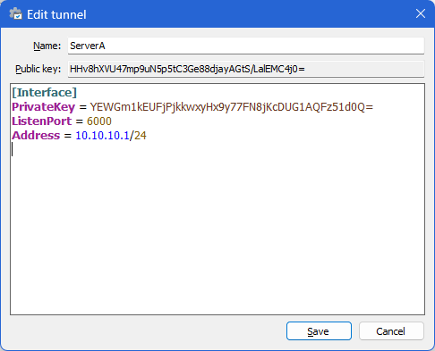
Among them, Public Key and Private Key are automatically generated key pairs; you only need to configure the listening port and the virtual address.
Address specifies Node A's IP within the virtual network; ListenPort is the port A listens on. Ensure this port is allowed in Windows Firewall and the router (if applicable).
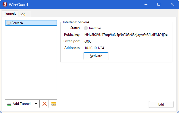
After saving, the configuration will look like the example shown below. Note that the configuration is not yet complete—Node B's public key will be added later.
3. Configure Node B (Client Node)
Node B, as the device that initiates the connection, needs to know who to connect to and its own virtual IP.
Edit the configuration file: In the WireGuard main interface, select Node B's tunnel, click "Edit," and add the following content.
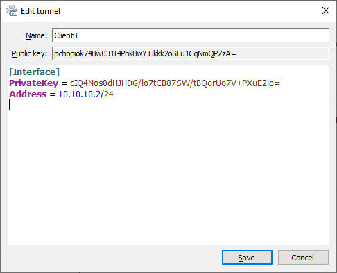
Among them, PrivateKey and PublicKey are automatically generated; Address is set by yourself.
4. Add Each Other to Peer Lists
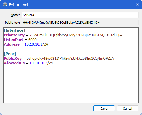
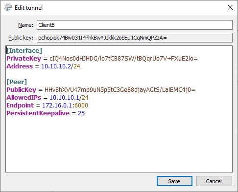
Now that both A and B have their own key pairs, the next step is to add each other's public keys to their respective Peer lists. The added form is as follows:
-
Node A:
-
Node B: As the active connection initiator, Node B adds two additional items: Endpoint and PersistentKeepalive.
-
-
Endpoint specifies Node A's public IP and listening port.
-
AllowedIPs = 10.10.10.1/24 controls the packet matching rules for outbound/inbound traffic handled by the WireGuard driver.
-
PersistentKeepalive = 25 ensures B sends keepalive packets every 25 seconds to maintain NAT mappings, allowing A to actively send data to B.
-
5. Start and Verify the Connection
-
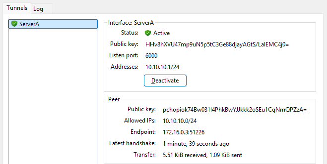
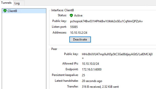
Startup sequence: Connect Node A (public node) first, then Node B.
-
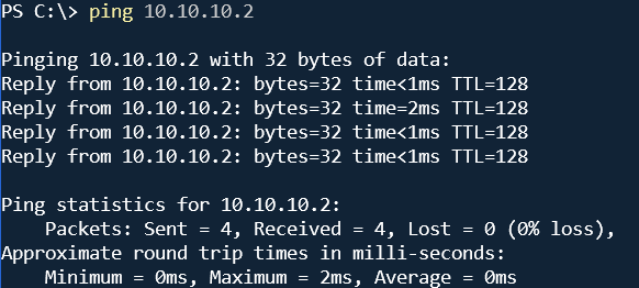
Verification method: Ping each other's virtual IP from Node A and Node B. If successful, the connection is working.